Showing posts with label imp. Show all posts

Thursday, November 22, 2012

The need of clocking blocks in testbench

The need of clocking blocks?
Clocking blocks have been introduced in SystemVerilog to address the problem of specifying the timing and synchronization requirements of a design in a testbench.
1) It is used to specify synchronization characteristics of the design
2) It Offers a clean way to drive and sample signals
3) It provides race-free operation if input skew > 0
4) It helps in testbench driving the signals at the right time
5) Features
    - Clock specification
    - Input skew,output skew
    - Cycle delay (##)
6) Can be declared inside interface,module or program

Example :
01.Module M1(ck, enin, din, enout, dout);
02.input         ck,enin;
03.input  [31:0] din    ;
04.output        enout  ;
05.output [31:0] dout   ;
06. 
07.clocking sd @(posedge ck);
08.input  #2ns ein,din    ;
09.output #3ns enout, dout;
10.endclocking:sd
11. 
12.reg [7:0] sab ;
13.initial begin
14.sab = sd.din[7:0];
15.end
16.endmodule:M1


#Skew : it is related to set up and hold time.

Input and Output Skew :
A skew number for an input denotes when that input is sampled before the clocking event (such as posedge or negedge) occurs. 
For an output, it is just the opposite - it denotes when an output is synchronized and sent after the clocking event.

clocking clock1 @(posedge clk1);
   input a1, a2;
   output b1;
endclocking
In this case, the default input skew is 1step and the default output skew is 0.

Overwriting default skews

Even if there is a default statement for skews in a clocking block, it can be overwritten later in the block. For example, the example below overwrites the default input skew for signal a1 (to 1step) and output b1 (to 5 ns), but the input skew for a2remains unchanged at 2 ns.
 
clocking clock1 @(posedge clk1);
   default input #2ns output #3ns;
   input #1step a1;
   input a2;
   output #5ns b1;
endclocking


Monday, April 9, 2012

Synchronous Reset vs Asynchronous Reset

Why Reset?

A Reset is required to initialize a hardware design for system operation and to force an ASIC into a known state for simulation.

A reset simply changes the state of the device/design/ASIC to a user/designer defined state. There are two types of reset, what are they? As you can guess them, they are Synchronous reset and Asynchronous reset.

Synchronous Reset

A synchronous reset signal will only affect or reset the state of the flip-flop on the active edge of the clock. The reset signal is applied as is any other input to the state machine.

Advantages:
  • The advantage to this type of topology is that the reset presented to all functional flip-flops is fully synchronous to the clock and will always meet the reset recovery time.
  • Synchronous reset logic will synthesize to smaller flip-flops, particularly if the reset is gated with the logic generating the d-input. But in such a case, the combinational logic gate count grows so the overall gate count savings may not be that significant.
  • Synchronous resets provide some filtering for the reset signal such that it is not affected by glitches unless they occur right at the clock edge. A synchronous reset is recommended for some types of designs where the reset is generated by a set of internal conditions. As the clock will filter the logic equation glitches between clock edges.
Disadvantages:
  • The problem in this topology is with reset assertion. If the reset signal is not long enough to be captured at an active clock edge (or the clock may be slow to capture the reset signal), it will result in failure of assertion. In such case, the design needs a pulse stretcher to guarantee that a reset pulse is wide enough to be present during the active clock edge.
  • Another problem with synchronous resets is that the logic synthesis cannot easily distinguish the reset signal from any other data signal. So proper care has to be taken with logic synthesis, else the reset signal may take the fastest path to the flip-flop input thereby making worst-case timing hard to meet.
  • In some power saving designs, the clocked is gated. In such designed only asynchronous reset will work.
  • Faster designs that are demanding low data path timing, can not afford to have extra gates and additional net delays in the data path due to logic inserted to handle synchronous resets.
Asynchronous Reset

An asynchronous reset will affect or reset the state of the flip-flop asynchronously i.e. no matter what the clock signal is. This is considered as high priority signal and system reset happens as soon as the reset assertion is detected.

Advantages:
  • High speeds can be achieved, as the data path is independent of a reset signal.
  • Another advantage favouring asynchronous resets is that the circuit can be reset with or without a clock present.
  • As in synchronous reset, no workaround is required for logic synthesis.
Disadvantages:
  • The problem with this type of reset occurs at logic de-assertion rather than at assertion like in synchronous circuits. If the asynchronous reset is released (reset release or reset removal) at or near the active clock edge of a flip-flop, the output of the flip-flop could go metastable.
  • Spurious resets can happen due to reset signal glitches.
Conclusion

Both types of resets have positives and negatives and none of them assures fail-proof design. So there is something called "Asynchronous assertion and Synchronous de-assertion" reset which can be used for best results.

source: internet and my experience 

Ethernet and more

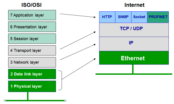
Ethernet is a protocol under IEEE 802.33 standard User Datagram Protocol (UDP) UDP is a connectionless transport protocol. I...