Friday, July 21, 2017

Working with GIT : Basic Commands

What is GIT :
  1. Git is a version control system (VCS) for tracking changes in computer files and coordinating work on those files among multiple people. 
  2. It is primarily used for source code management in software development, but it can be used to keep track of changes in any set of files 
  3. Git was created by Linus Torvalds in 2005 for development of the Linux kernel, with other kernel developers contributing to its initial development. Its current maintainer since 2005 is Junio Hamano. 
  4. As with most other distributed version control systems, and unlike most client–server systems, every Git directory on every computer is a full-fledged repository with complete history and full version tracking abilities, independent of network access or a central server. 
  5. Like the Linux kernel, Git is free software distributed under the terms of the GNU General Public License version 2. 


Basic Commands :

  1. git clone <repo path> Clone a repository into a new directory 
  2. git status  - Show the working tree status like file a is modified and file b is newly added. 
  3. git add <file name> - Add file contents to the index 
  4. git commit -m “message1” - Record changes to the repository 
  5. git pull – Fetch from and integrate with another repository or a local branch (fetch + merge)   Git pull is useful when you are working on your local branch and you want to merge your changes with the latest central repo.                                                                                       Note1: Before using git pull, always commit your changes 1st so that it may merge with central repo.                                                                                                                                       Note2: Before using git commit we need to use git add. 
  6. git checkout <file A> – it will revert your all changes of file A in local branch 
  7. git blame <file A> - it will show all the modification done to file A with the person name , time and line no. It helps to migrate changes done by a particular person in file A, to another file or project. 


Sunday, June 4, 2017

Assertion

1. An Assertion specifies the behaviour of the system.
2. It validates the behaviour of design 
3. In addition, assertion can be used to provide functional coverage and generate input stimulus for validation


The advantage of assertion:
1. Improving observability 
2. reduce the debug time 
3. bugs can be found earlier and more isolated 
4. can interact with C function


types of assertion:
1.Immediate 
2. concurrent 


Immediate                                                                concurrent                            

based on simulation event                                       based on a clock cycle 
used without property keyword                                used with property keyword
placed in procedure block definition                        placed in procedural blocks, modules, interfaces or program                                                                                     definition

i) Immediate assertions are useful for combinational expression, similar to if else statement but with assertion control.
ii) Assertions are non-synthesizable
iii) Assertions can be written in design and TB both but in design, while synthesising need to remove so use `define


Difference between assert and cover :

assert: if you want scenario to be hold true then you write an assertion.
cover : Whether scenario ever happened in your simulation or not.


|-> implication operator


sequence s;
    @(posedge clk) a ##1 b;
  endsequence
 
  property p;
    a |-> s;
  endproperty
 
  assert property (p);
  cover property (p);

Monday, March 20, 2017

X Propagation


1. Hardware description languages such as SystemVerilog use the symbol 'X' to describe any unknown logic value.
2. If a simulator is unable to decide whether a logic value should be a '1', '0', or 'Z' for high impedance, it will assign an X. This causes problems for two reasons. The first is that an X may be converted inadvertently(accidently) to a 'known' state by overly optimistic simulation code. The second is that gate simulators can generate excess X values because they generally apply more pessimistic rules.

3. The situation is not helped by the traditional use of the X to express 'don't-care' conditions for the purposes of synthesis, as well as for an unknown state in simulation.

X states can propagate through a simulation, multiplying uncertainty and potentially hiding bugs.

This has become a bigger issue in recent years because of the use of power-gating architectures to save energy. In this design approach, when the logic is powered down, it no longer provides a reliable signal to downstream logic, which itself may not have been designed to cope properly. This propagates errors through the chip when the blocks move between power states. However, any logic block that has not been properly reset may also generate X values.
Over-optimistic simulation

For example, a simulator will apply an X to any memory location that has not been initialized. Reset logic is expensive, particularly in terms of routing overhead, so it will rarely be feasible to apply a reset to every memory element at restart. Logic that has been designed with uninitialized memories and a weak reset strategy may be prone to more undiscovered bugs due to X propagation.

A common source of unwanted X optimism is when downstream logic states are assigned using 'if-then-else' or 'case' statements. Because the X state will not satisfy the logic test, the block will be assigned the default case. This may convert the X to a 'known' value or propagate it further into the simulation, masking a bug.

X pessimism can happen when signals converge, for example in a multiplexor. The simulator has to assign the X value to the output if presented with an X on an input that is not overridden by other known signals feeding into the block.
Simulation tweaks

There are a number of ways of dealing with X propagation. One is to analyze the waveform generated by a simulator – many simulators color-code these signals to make them easier to pick out. However, this involves painstaking manual inspection and design insight to work out whether the X is dealt with correctly or not.

Some simulators can be set up to generate random values in place of Xs, on the basis that differences in behaviour with otherwise identical input vectors should point to X propagation issues. However, the errors caused by X propagation can be subtle and only turn up in rare cases, which may not be encountered during most simulation runs. Another possibility is more exhaustive simulation.

The 'xprop' simulation technology employed by recent versions of Synopsys' VCS will replace every X it encounters with both a 0 and 1 to calculate all possible values, and then merge them to decide which value should be driven to the output. VCS employs a number of merge techniques to reflect different expectations, including a pessimistic approach more akin to gate-level simulation, and a more hardware-like scenario in which any output that cannot be merged to a known value is converted to an X.

The CVC simulator from Tachyon-DA takes the approach of changing default Verilog semantics to a situation in which it works on the assumption that any X should be treated as a 0, 1 or X.
X prevention

On the basis that prevention is better than cure, Mike Turpin's seminal 2003 SNUG Boston paper "The dangers of living with an X" contained a number of recommendations for writing HDL that is more likely to avoid X propagation, as well as advice on verification techniques:


"For one-hot logic on a critical path, write the RTL directly in a sum-of-products form (rather than case) and add a one-hot assertion checker.

"Avoid using if-statements, as they optimistically interpret Xs. Instead use ternary (that is, conditional ?) operators or priority-encoded case statements.
"For case statements, cover all reachable 2-state values with case-items and always add a default (but only use it to assign Xs, to avoid X-optimism)."

However, for complex control logic, it can be difficult to be sure that these coding technique lead to an X accurate, rather than X optimistic or X pessimistic, design.
X detection

Some of these issues can be detected by linting tools such as Ascent Lint. Cadence Design Systems is working on a combination of formal techniques that will yield what the company currently calls "super linting", and which will form part of a range of verification 'apps'.

Source : Internet 

Thursday, December 22, 2016

Multiple-Commands-in-one-line

This is how we can give multiple commands in one line

A; B    Run A and then B, regardless of success of A
A && B  Run B if A succeeded
A || B  Run B if A failed

A &     Run A in background.


Source : Internet

Friday, September 9, 2016

RTL to GSD2 flow

GLS : gate level simulation


1. GLS is a step in the Design flow to ensure that the design meets the functionality after placement and routing.

2. What all inputs are needed to perform GLS: we Need post-routed netlist, Testbench, SDF (standard delay format file).

3. SDF is meant for Standard Delay format which will have all the delay information for the cell and the wire.

4. To generate SDF: we read in the routed netlist and the Extracted parasitics file(from Extraction Tool say StarRC extraction from Synopsys Inc, SPEF [ Standard Parasitics Extraction Format]).

5.Q .I have a doubt, say if I perform Formal Verification say Logical Equivalence across Gatelevel netlists(Synthesis and post routed netlist). Do you still see a reason behind GLS.

Answer: If we have verified the Synthesized netlist functionality is correct when compared to RTL and when we compare the Synthesized netlist versus Post route netlist logical Equivalence then i think we may not require GLS after P & R(placing and routing). But how do we ensure on Timing sir. To my knowledge, Formal Verification Logical Equivalence Check does not perform Timing checks and don't ensure that the design will work on the operating frequency, so still, I would go for GLS after post route database.


6. Q : I partially agree, say I perform Static Timing Analysis, after post route, I take the post routed netlist and the extracted parasitics file and the Design timing constraints and perform the Design timing checks say all possible checks(setup/hold/clockgating/…) do you still see a reason for GLS after post route.


Answer: I agree STA will check all the possible cases and corners and place the chip in different modes and things like that. But still see that GLS is a super-set over STA.

if by mistake the designer has placed timing exceptions like false-paths,multi-cycle paths, then how we ensure that the design will meet timing requirements, so i feel ,that there should be some mechanism to validate as a counter check, so i still feel GLS is needed after post route design sir.if the design is not synchronous friendly and purely asynchronous design then our STA will not favour us much.I still feel one more reason for GLS is how to ensure that the design will be out of reset and our reset sequences and initialization sequences, boot-ups are fine. So I feel GLS is mandatory though it has limitations of Ensuring the quality of test vectors.

Ensuring that the vectors will cover the complete area of the design (what i mean is the coverage analysis) and simulation run-time and things like that GLS ensure that the “Guarantee for Design Meeting for Functionality”

Gate level simulation represents a small slice of what should actually be tested for a tape-out. They offer a warm feeling that, what you are going to get back will actually work and secondly, they offer some confidence that your static timing constraints are correct.

But the common reason to go for a gate level simulations are as follows:
To check if the reset release, initialization sequence and boot up sequences are proper.
STA tools doesn't verify the asynchronous interfaces.
Unintended dependencies on initial conditions can be found through GLS
Good for verifying the functionality and timing of circuits and paths that are not covered by STA tools
Design changes can lead to incorrect false path/multi cycle path in the design constraints.
It gives an excellent feeling that the design is implemented correctly

So before shipping a design to tape-out, we run a limited set of gate level simulations. Because there are some difficulties associated with this GLS, they are:
Takes a lot of setting up and debugging
Takes a huge amount of computing recourses ( CPU time and disk space for storing wave)
RTL simulations alone take multiple days of run time even for a single regression. GLS takes 10* times.
Generation of debug data (VCD, Debussy) is impossible with GLS

In my opinion, the gate-level simulations are needed mainly to verify any environment and initialization issues.

Source: Internet 

Saturday, June 4, 2016

Programming block and Module

always begin 
       @(posedge clk) $display("at the posedge of clk");
       end
and
initial begin 
          forever @(posedge clk) $display("at the posedge of clk");
       end
It is mainly a difference in intent. Some synthesis tools ignore all the code in an initial block thinking they are for simulation only and do not describe hardware to be synthesized.
Technically, there are a few thing you can do with a forever statement that you cannot do with an always block. As a looping statement, you can break out of aforever loop, and if you name the statement, you can disable it. So you can terminate the process created by an initial block. There is no way to terminate the process created by an always block.

Program Block :
The program block came from the Vera verification language that was donated to SystemVerilog. In Vera, a program was a single procedure that represented the "test". Your test was started at time 0 and when the test terminated, the program terminated the simulation. If you needed multiple test threads, you either had to use the fork statement to start it, or use multiple programs. When the last program terminated, the simulation terminated.
As part of the integration with SystemVerilog, the program was turned into a module-like construct with ports and initial blocks are now used to start the test procedure. Because an always block never terminates, it was kept out of the program block so the concept of test termination would still be there.
Today, most people do not utilize this termination feature because the OVM/UVM have their own test termination mechanisms. The program block is no longer a necessary feature of the language other than to help people converting over from Vera to SystemVerilog.
A module can have always block .
Example :
program test;
 initial 
   begin
     fork
       $display($time, " a");
       #10 $display($time, " b");
       #20 $display($time, " c");
       $display($time, " d");
     join_none
     $display($time, " e");
   end
endprogram

Output : 
0 e
0 a
0 d
module test;
 initial 
   begin
     fork
       $display($time, " a");
       #10 $display($time, " b");
       #20 $display($time, " c");
       $display($time, " d");
     join_none
     $display($time, " e");
   end
endmodule

Output : 
0 e
0 a
0 d
10 b
20 c


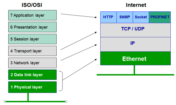
Ethernet and more

Ethernet is a protocol under IEEE 802.33 standard User Datagram Protocol (UDP) UDP is a connectionless transport protocol. I...